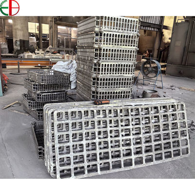
Custom Cast Furnace Loading Frames for Heat Treatment Lines
Cast furnace frames and grid trays from the EB Castings product range. Individual frame geometry is specified for the intended furnace installation.
Product Specifications
Product type: Cast furnace loading frame
Material family: Heat-resistant cast steel
Alloy grade: Selected for the specified thermal cycle and atmosphere
Overall dimensions: To approved installation drawing
Load arrangement: Defined by component positions and support layout
Tray interfaces: To mating tray and support dimensions
Handling features: According to the approved lifting or transfer arrangement
Inspection: Drawing dimensions and agreed material requirements
Optimized Furnace Load Support Systems
A furnace loading frame brings trays, supports and workpieces into a repeatable arrangement during heat treatment. EB Castings supplies custom cast frames for furnace installations where the fixture must fit the working envelope, transfer equipment and production load. This product is intended for projects requiring a drawing-defined frame rather than a standard basket selected only by outside length and width.
The frame provides the structural interfaces around which the load is assembled. Its rails, cross-members and contact areas determine where the supported parts or trays bear on the fixture. A clear arrangement helps production teams reproduce the intended positioning from one batch to the next and gives maintenance staff identifiable surfaces to inspect as the fixture remains in service.
Heat-Resistant Cast Steel Engineering
Material selection starts with the thermal cycle and the furnace environment. Heating temperature, time at temperature, cooling practice and atmosphere all influence the suitability of a heat-resistant casting alloy. A fixture used through repeated heating and cooling should therefore be specified for its actual operating conditions, rather than assigned a temperature capability from an unrelated material table.
The casting design and alloy choice work together. Section transitions, unsupported lengths and contact positions affect how loads pass through the frame. For a replacement project, the existing drawing provides a useful starting point; photographs of distortion, cracking or worn supports help identify the areas that deserve additional engineering review before the next frame is ordered.
Practical Assembly Interfaces
Successful installation depends on more than the outer envelope. Tray seats must align with the mating equipment, support heights must suit the load arrangement, and lifting or transfer interfaces must correspond to the equipment used on the line. Where a frame carries removable trays, their seating surfaces and locating details should be defined together so that one part is not specified independently of the other.
Access for loading and unloading also matters. Components need an intentional position within the frame, with suitable clearance around adjacent parts and the surrounding equipment. Open areas can be incorporated into the arrangement to suit the process, while support members remain positioned to carry the intended load. Final spacing and allowable loading belong on the approved assembly documentation.
Replacement and New Installation Applications
Typical enquiries include replacement furnace carriers, frames used with cast trays, and loading assemblies for industrial heat treatment. For repeat replacements, maintaining consistent interface dimensions can be as important as matching the overall shape. For a new installation, the frame should be reviewed alongside the chamber envelope, transfer path and workpiece arrangement before production details are released.
Inspection priorities include overall dimensions, support locations, seating levels and any drawing-specified machined areas. Material identification and additional examination requirements can be included in the order specification. A documented arrangement also provides a useful reference for later checks, allowing maintenance teams to compare the used frame with the intended support positions.
Request Your Custom Furnace Frame Quotation
Send the frame drawing, mating tray details, operating cycle and proposed load arrangement for a project-specific quotation. Include photographs of the current assembly when replacing an existing frame. Bring the fixture, furnace and handling requirements together in one clear specification, and give your next loading assembly a practical starting point.
Custom Cast Furnace Loading Frames for Heat Treatment Lines
Cast furnace frames and grid trays from the EB Castings product range. Individual frame geometry is specified for the intended furnace installation.
Product Specifications
Product type: Cast furnace loading frame
Material family: Heat-resistant cast steel
Alloy grade: Selected for the specified thermal cycle and atmosphere
Overall dimensions: To approved installation drawing
Load arrangement: Defined by component positions and support layout
Tray interfaces: To mating tray and support dimensions
Handling features: According to the approved lifting or transfer arrangement
Inspection: Drawing dimensions and agreed material requirements
Optimized Furnace Load Support Systems
A furnace loading frame brings trays, supports and workpieces into a repeatable arrangement during heat treatment. EB Castings supplies custom cast frames for furnace installations where the fixture must fit the working envelope, transfer equipment and production load. This product is intended for projects requiring a drawing-defined frame rather than a standard basket selected only by outside length and width.
The frame provides the structural interfaces around which the load is assembled. Its rails, cross-members and contact areas determine where the supported parts or trays bear on the fixture. A clear arrangement helps production teams reproduce the intended positioning from one batch to the next and gives maintenance staff identifiable surfaces to inspect as the fixture remains in service.
Heat-Resistant Cast Steel Engineering
Material selection starts with the thermal cycle and the furnace environment. Heating temperature, time at temperature, cooling practice and atmosphere all influence the suitability of a heat-resistant casting alloy. A fixture used through repeated heating and cooling should therefore be specified for its actual operating conditions, rather than assigned a temperature capability from an unrelated material table.
The casting design and alloy choice work together. Section transitions, unsupported lengths and contact positions affect how loads pass through the frame. For a replacement project, the existing drawing provides a useful starting point; photographs of distortion, cracking or worn supports help identify the areas that deserve additional engineering review before the next frame is ordered.
Practical Assembly Interfaces
Successful installation depends on more than the outer envelope. Tray seats must align with the mating equipment, support heights must suit the load arrangement, and lifting or transfer interfaces must correspond to the equipment used on the line. Where a frame carries removable trays, their seating surfaces and locating details should be defined together so that one part is not specified independently of the other.
Access for loading and unloading also matters. Components need an intentional position within the frame, with suitable clearance around adjacent parts and the surrounding equipment. Open areas can be incorporated into the arrangement to suit the process, while support members remain positioned to carry the intended load. Final spacing and allowable loading belong on the approved assembly documentation.
Replacement and New Installation Applications
Typical enquiries include replacement furnace carriers, frames used with cast trays, and loading assemblies for industrial heat treatment. For repeat replacements, maintaining consistent interface dimensions can be as important as matching the overall shape. For a new installation, the frame should be reviewed alongside the chamber envelope, transfer path and workpiece arrangement before production details are released.
Inspection priorities include overall dimensions, support locations, seating levels and any drawing-specified machined areas. Material identification and additional examination requirements can be included in the order specification. A documented arrangement also provides a useful reference for later checks, allowing maintenance teams to compare the used frame with the intended support positions.
Request Your Custom Furnace Frame Quotation
Send the frame drawing, mating tray details, operating cycle and proposed load arrangement for a project-specific quotation. Include photographs of the current assembly when replacing an existing frame. Bring the fixture, furnace and handling requirements together in one clear specification, and give your next loading assembly a practical starting point.